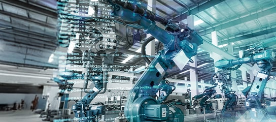
Sensor Data Fusion in Industry 4.0
For systems to achieve some degree of autonomy, they must actively use different sensory information sources.
Sensor Data Fusion in Industry 4.0
For systems to achieve some degree of autonomy, they must actively use different sensory information sources.

The development of sensor data fusion has come from the realisation that there are limitations to reconstructing environmental information using a single source of sensor information. Sensor data fusion merges the benefits of various sensors, offering insights that individual independent sensors cannot generate. A system composed of multiple sensors combines information from different sources into a consistent and robust outcome. Data fusion increases accuracy, measurement reliability, and range. The use of Sensor data fusion in industry 4.0 presents innovative solutions to advanced and smart manufacturing processes. This article discusses multi-sensor measurement and data fusion technology and its applications in precision monitoring systems.
Figure 1 shows the general framework of an intelligent system with multi-sensor capabilities. The sensors in a multi-sensor system feed individual measurement data to the data fusion layer. This data fusion layer uses advanced signal processing algorithms to combine the individual information into a whole. The control application simultaneously sends control signals to the actuator. Multi-sensor data fusion integrates the measurement data from all sensors to offer a comprehensive system overview.

Figure 1: Framework for intelligent systems
Data fusion fully uses multiple information streams by combining redundant or complementary information from different sources. This information must be of specific standards to obtain a consistent interpretation or description of the tested object so that the system performs better than the system composed of each subset it contains.
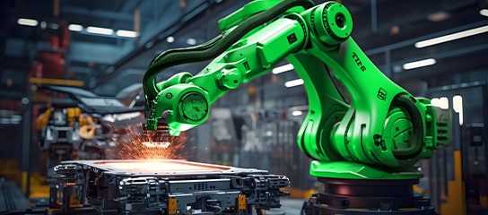
In recent years, multi-sensor data fusion has seen wide use in both military and civilian fields. This technology finds use in command, control, communications, and intelligence systems; complex industrial process control; robotics; automatic target recognition; traffic control; inertial navigation; ocean surveillance and management; agriculture; remote sensing; medical diagnosis; image processing; pattern recognition; and other fields.
The following figure shows the multiple sensor data fusion structure based on industry applications.

Figure 2: Structure of multi-sensor data fusion
The multi-sensor system (comprising n sensors) fuses the information obtained from the object and its environment. The system develops m fusion nodes to fuse n pieces of information. The information output from sensor 1 (S1) and sensor 2 (S2) fuses onto information S_12 in fusing node 1. This fused information further fuses into S_123 with the information of sensor3 in node 2. The fusing continues until all information from n sensors is fused, resulting in information S. The fusing database receives this information S. This fusing database (a part of the database of the whole intelligent control system) stores the results of the information fusion. A few specifications for the above fusing process are as follows:
The modules (extreme right boxes) mentioned in figure 2 have the following names and specifications:

Figure 3: ART-2 neural network
The bottom layer of the neural network accepts the input information from the object and environment, with one input unit receiving an element of the input pattern vector. The unit at the top is a prototype and provides the cluster class of a similar input pattern. The interconnecting value between the bottom and top layers records the features of the input data. The principles of ART – 2 are based upon the mechanism of competitive learning: an input pattern applied to the network is pre-processed by the network with filtering, increasing contrast and unification. You can then compare the pattern with the prototype. The winner is the one that most resembles the input prototype. If the similarity between the winner and the input is greater than the pre-chosen warning parameter, learning is needed, and the weight value of the winner is revised to show the features of the input pattern.
Conversely, if the similarity is less than the minimum warning parameter, the current winner is emptied, and the search process repeats. If no winner exhibits similarity with the input, a new unit is established on the top layer and made a prototype similar to the input by learning. In this way, the port on the top layer corresponds with a type of input information class, thus completing the combination of the input modes and realising the fusion of the input information.
The fusion methods or strategies classify into low, medium, and high levels. These three levels differ in the complexity of processing inputs from data sources.
Low-level data fusion (LLDF) is the simplest technique to realise a combination of inputs. Low-level data is rearranged into a new data matrix, where the variables, extracted from different sources, are successively placed. The combined data matrix variables are the sum of the previously separated data sets. The concatenated data, in most cases, is then pretreated before the final creation of the classification or regression model. However, it is possible to conduct specific elementary operations before putting them together.
Medium-(mid-) level data fusion (MLDF) or “feature-level" fusion eliminates the insufficiently diverse, non-informative variables from the datasets. It is based on a preliminary feature extraction that continues to maintain the relevant variables. You can use the developed algorithms to choose these features before merging them into one matrix that finds use in a chemometric method.
High-level data fusion (HLDF) works on a decision level. These models are regression models that provide continuous responses for the classifications or input data, deciding the class membership of the new samples. The combination of decisions from these models forms a complex model that can create the final estimation. HLDF may unify the outputs in one decision model to arrive at a better estimate.

Figure 4: Comparison of fusion methods
The following figure shows a multi-sensor system that includes an ultraviolet/visible (UVV) visual sensor, an x-ray visual imaging sensor, a laser reflective photoelectric sensor, a spectral graph, a visible light photoelectric sensor, and an auxiliary illumination visual sensor. You can use all these sensors during laser welding for timely detection and analysis.
Figure 5: Sensor fusion in laser welding
The trigger sensor can simultaneously synchronise the multi-sensing and welding systems. This sensor connects to a signal box and provides a trigger signal for the laser machining and sensing systems. The high-speed camera sensor with the visual induction filter can also obtain metal spatters and plume images. The characteristics undergo analysis by obtaining the molten pool images with a 40W diode laser of 976 nm wavelength and the narrow band filter high-speed camera equipped with a narrow band filter. The welding areas' light intensity transmits to the optical splitter by connecting two fibres to the laser head. The two respective photoelectric sensors can obtain the light and laser reflection intensity. The x-rays that emit from the weld's left side can penetrate the entire welding area. Differing material density causes the different degrees of attenuation of x-rays. The spectrometer collimator focuses on the plasma area. The collimator is placed at the front of the welding direction and receives spectral information via the optical fiber.
Farnell has partnered with many different suppliers catering to a wide range of Industrial Sensors and Sensor Connectors Components products and solutions portfolios, such as Current Sensors, Environmental Sensors, Flow Sensors, Light Sensors, Magnetic Sensors, Liquid Level Sensors, Motion Sensors & Position Sensors, Particle Sensors, Pressure Sensors Transducers, Temperature Sensors, Ultrasonic Sensors, and Vibration & Shock Sensors. Farnell is available for design execution, development, and projects.
One of the greatest revolutions in all of human history! AI is an all-encompassing concept that incorporates human intelligence into machines
The #1 Destination for Embedded Evaluation Boards, Development Kits, and Tools
Explore our well-curated library of whitepapers, technical articles, videos, training modules, tutorials, and more to support you in developing your designs, business, and career